Hey there, if you’re here, you’re probably deep in the weeds of a project that needs a toroidal inductor—and not just any random one, but one that fits your exact needs perfectly. As someone who’s spent the last 12 years selling toroidal inductors to everyone from small solar tech startups to big-name EV makers, I’ve seen way too many folks pick a “close enough” off-the-shelf part and end up kicking themselves later when it overheats, wastes power, or doesn’t fit where they need it. Today, I’m walking you through the actual steps to optimize a toroidal inductor for your specific application—no overly jargon-heavy nonsense, just real-world stuff I’ve learned fixing people’s messes and tuning inductors right the first time. Toroidal Inductor
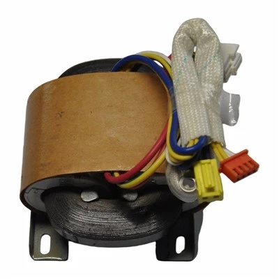
First off, let’s get one thing straight: toroidal inductors aren’t just smaller versions of other inductors. Their donut shape gives them built-in advantages—less electromagnetic interference (EMI) because the magnetic field wraps tight around the core, fewer stray losses, and they pack more inductance into less space than a comparable core from a regular E-I or pot core. But those perks only show up if you design or tweak them for your use case, not a generic one. So let’s start with the non-negotiable stuff: figuring out exactly what your application needs from this inductor. If you skip this, you’re guessing, and guessing leads to bad parts.
Let’s break down that first step—requirements gathering—because it’s make-or-break. I’ve had a customer come to me last year, a robotics startup, asking for a toroidal inductor for their joint motor drive, and they just said “make it work for our 48V system.” Turns out, their motor was switching at 20kHz, pulling a peak current of 12A, and the inductor had to fit in a 10mm x 15mm space inside the joint housing. If I’d just made a standard 48V/10A part, it would have been too big, overheated, and caused EMI that messed with their motor encoders. So don’t be that guy (or gal)—write down every single spec, no matter how small. The big ones are inductance value, current (both RMS and peak, that’s huge—most people forget peak current and only check RMS), operating frequency, ambient temperature range, and physical size constraints. Oh, and if it’s going in something like a medical device or an EV, you might have compliance stuff—like RoHS, or temperature ratings up to 125°C for under-hood parts. I always tell customers to jot down even the weird edge cases, like “it will get jostled during shipping, so lead strength matters” or “it has to sit next to a sensitive sensor, so EMI can’t be more than X µT.”
Next up: picking the right core material. This is where I see 50% of optimization go wrong. The core is the heart of the inductor, and different materials behave totally different at different frequencies and currents. Let’s keep this simple—no deep material science lectures. If your application is low frequency, like power supplies for off-grid solar (say 50/60Hz) or line filters, ferrite cores are too lossy. You want something like powdered iron or grain-oriented silicon steel—they handle high currents at low frequencies without wasting power as heat. But if you’re switching at high frequencies, like EV chargers (100kHz+) or small DC-DC converters in phones/robots, ferrite is your go-to. Wait, but not all ferrites are equal—there’s different grades: Mn-Zn for high frequency, Ni-Zn for even higher up in MHz ranges. Last month, a customer doing a 1MHz wireless charger tried a cheap Mn-Zn core and their inductor got so hot it melted the adjacent plastic. Switched to Ni-Zn, and problem gone. Also, if you’re dealing with really high DC current, like traction motor inductors for EVs, you need a core that can handle saturation—powdered iron has a higher saturation point than ferrite, so that’s non-negotiable there. Saturation is when the core gets so magnetized it stops working, so if your peak current gets above the core’s saturation rating, your inductance drops through the floor and your circuit goes haywire. That’s a costly mistake— I had a wind turbine builder learn that the hard way when their 100A peak inductor saturated during wind gusts, costing them a week of downtime.
Once you’ve got the core material locked in, it’s time to size the core and pick the wire gauge. For this, we use a formula called the area product (AP) method, but I’m not gonna make you do math you’ll forget. The quick and dirty way I teach customers is: if you have higher current, you need a bigger core and thicker wire. But wait—thicker wire isn’t always best, especially at high frequencies. Skin effect is a thing: at frequencies above a few kHz, current doesn’t flow evenly through the wire, it flows mostly on the surface. So a single thick wire at 20kHz will have more AC resistance than multiple thinner wires twisted together (that’s litz wire, by the way). That’s a trick I use all the time. For example, a customer doing a 50kHz DC-DC converter had a 10A RMS current, and tried using a single 12AWG wire— it got hot because of skin effect. Switched to 4 strands of 18AWG litz wire, and the AC resistance dropped by 30%, no more overheating. Also, don’t forget the window area of the toroid—the space in the middle where you wrap the wire. You need to leave enough room for the wire, insulation, and maybe even a shield if you need to cut down EMI. If you cram too much wire in there, it’s hard to wind, insulation can rub through, and you get more losses.
EMI is another big one for optimization, especially if your application is near sensitive electronics. Toroids already have lower EMI than other core shapes, but you can tweak them even more. First, the winding method: if you wind the wire evenly around the entire toroid (not just one side), that cancels out a lot of the stray magnetic field. I always tell customers to use “uniform winding” — start at the inner edge, wind all the way around to the outer edge, then keep going, no skipping. That cuts stray flux by like 70% compared to lopsided winding. If you need even less EMI, add a shield between the winding and the core—usually a copper foil or conductive tape. Just make sure the shield isn’t a closed loop, because that would act like a shorted turn and cause losses. I’ve had a satellite component customer ask for zero EMI, so we used a half-loop copper shield and their test results were perfect—no interference with the satellite’s communication system. Also, the leadouts matter: keep the leads short and twisted together if they’re carrying AC, that reduces stray field too.
Loss minimization is the name of the game too—you don’t want your inductor turning your battery power into heat, right? There are two main losses: core losses (from the core material) and copper losses (from the wire). We already talked about picking the right core and using litz wire for high frequencies to cut copper losses, but another trick is gaping the core. Wait, toroidal cores are usually gap-free, but if you need to increase the inductance or lower the sensitivity to saturation, you can add a small air gap in the core. The gap is usually a thin layer of insulation (like paper or plastic) between the core halves, not actually cutting a hole in the donut. That lets the core handle higher peak current without saturating, and it reduces core losses at high current levels. I did this for a customer building a 20kW solar inverter—they were getting too much core loss at peak load, so we added a 0.2mm gap to the ferrite core, and their efficiency went up 2.5%. That’s huge for inverters, where every percent of efficiency adds up to big energy savings over time.
Physical fit is non-negotiable too—even if your inductor has perfect electrical specs, if it doesn’t fit in the space you have, it’s useless. I’ve had more than one customer send me a CAD file of their enclosure, or even a photo, and say “the inductor has to fit here, that’s the only spot.” So I always adjust the core’s outer diameter, inner diameter, and height to match that space. Sometimes that means using a custom core size instead of an off-the-shelf one. For example, a customer making a portable power bank had a tiny space for the inductor, so we used a “low-profile” toroid—shorter height, slightly wider diameter, so it fit in the slim power bank body without sacrificing inductance or current rating. Just remember: if you make the toroid smaller, you have to trade off something—usually lower current or higher losses, so you have to balance based on your top priority. If size is #1, that’s your tradeoff; if efficiency is #1, you can go a bit bigger.
Another thing most people overlook: temperature and thermal management. Inductors get hot, and heat kills components faster. If your application is in a high ambient temp environment, like under the hood of a car, or a server rack that’s always running hot, you need to pick core and wire materials that can handle those temps. For example, high-temperature insulations for wire (like Kapton instead of regular enamel) that can go up to 180°C, and cores rated for high temps too. Also, if you’re mounting the inductor, make sure there’s a thermal path—glue it to a metal heatsink, or leave space for air flow. I had an EV customer whose inductor was mounted on a plastic bracket, and it got too hot because the plastic didn’t conduct heat. We switched to an aluminum bracket with thermal paste, and the inductor’s operating temp dropped by 20°C. That extended its lifespan way longer than if we’d just kept the plastic mount.
Wait, what about when you’re not sure about something? Testing is your best friend. I always build a prototype first before going into full production. For example, a customer building a medical device (critical, can’t have any failures) had a 50µH inductor for their pacemaker’s power supply. We built three prototypes, tested them at various currents, frequencies, and temps, and found a small issue with the winding that was causing EMI. We tweaked the winding pattern, tested again, and it passed all their medical compliance tests. Prototyping might cost a little extra upfront, but it saves you from recalls or redesigns later that cost way more. I can’t stress that enough—never skip prototyping for a critical application.
Also, don’t be afraid to customize off-the-shelf parts. A lot of customers think they have to go fully custom, but most of the time, you can tweak an existing core size, adjust the number of turns, change the wire, or add a gap to get exactly what you need without the high cost of a full custom mold. Last quarter, we had 12 customers who went that route, and it cut their lead times by half and their costs by 30% compared to full custom. That’s a win for everyone.
Let’s circle back to the big picture here: optimizing a toroidal inductor isn’t about following a rigid list of rules. It’s about balancing all your requirements—inductance, current, frequency, size, temp, EMI, cost—and picking the right tweaks for your specific use case. The biggest mistake I see is chasing one spec at the expense of all others: like picking the smallest size possible even if it means lower efficiency and higher heat, or picking the cheapest core even if it can’t handle the frequency. You have to prioritize. For EV traction inverters, peak current and efficiency are top, so you use powdered iron cores, litz wire, and size for those. For a line filter in an office machine, low cost and low EMI are top, so you use standard ferrite, uniform winding, and an off-the-shelf core that fits.
If you’re still stuck, don’t guess—reach out to someone who knows toroidal inductors, not just generic inductor design. As a toroidal inductor supplier, I’ve worked with hundreds of different applications, so I’ve probably seen something similar to what you’re dealing with. We can help you nail down your requirements, pick the right core, size it correctly, and prototype it fast, so you don’t waste time and money on parts that don’t work for you.
Wait, one last quick tip: if you’re looking to reduce cost, make sure you’re not overdesigning. For example, if your application only needs 5A RMS, don’t size the inductor for 10A “just in case”—that adds unnecessary material and cost. But also, don’t underdesign, like using a core that’s too small and will saturate. Balance is everything.
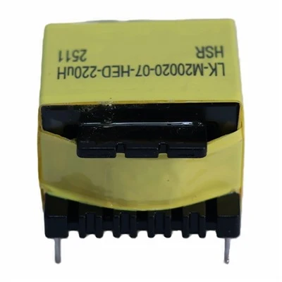
At the end of the day, the goal of optimizing your toroidal inductor is simple: get the performance you need, in the space you have, at a cost that works for your project, with no surprises down the line. I’ve been doing this long enough to know that a little extra time spent on the front end figuring out these details saves everyone headaches later. If you’re ready to stop dealing with generic inductors that don’t fit, or having to redo designs because of unforeseen issues, get in touch to talk through your specific needs. We can build exactly what you need, whether it’s a small low-power part for a sensor or a big high-current one for a solar inverter.
Power Transformer References
- Electromagnetic Compatibility Design Guide for Power Electronics Systems, IEEE Press
- Toroidal Inductor Design and Application Handbook, Magnetics, Inc.
- Skin Effect and Proximity Effect in High-Frequency Inductors, Texas Instruments Application Note SLVA785
- Power Inductor Core Material Selection, Coilcraft Technical Brief
Dongguan Hensiron Electric Co., Ltd.
As one of the most professional toroidal inductor suppliers in China, we have world-leading production equipment and strong manufacturing capabilities. Please feel free to buy high quality toroidal inductor made in China here from our factory. Customized orders are welcome.
Address: Building 4, Xinxing Industrial Zone, Wangao Road, Wanjiang Street, Dongguan City, China
E-mail: jessica@dghensiron.com
WebSite: https://www.dghensiron.com/
